
Beautiful Wiring Diagram Intermediate Light Switch diagrams digramssample diagramimages Check
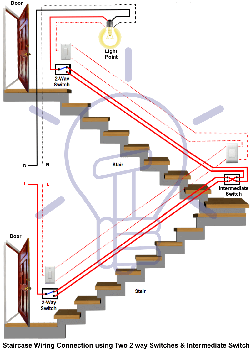
Simply defined, an intermediate switch is usually used in applications where three or more switches are used to control a single load or light. The switch allows you to control a single light from different positions. When you have three switches for controlling a single light, the switch a the middle will always be an intermediate switch.

Intermediate Light Switch Circuit Diagram
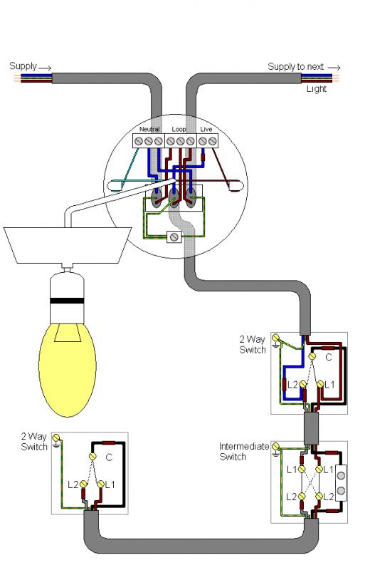
An intermediate switch is a switch which permits the control of a lighting point from three positions. In order to control this lighting point from the three positions, the intermediate switch is connected together with two other 2-way switches.

Great Two Way Intermediate Switch Circuit Diagram Rewiring A Bass Boat
Intermediate switching makes it possible to switch the same light(s) from multiple switches. They are very straight forward to terminate.This is a wiring/ter.

Wiring Diagram Intermediate Light Switch Wiring Digital and Schematic
An intermediate switch, also known as a three-way switch or crossover switch, is a type of electrical switch commonly used in multi-way lighting circuits. Unlike a standard two-way switch that provides simple on/off control from a single location, intermediate switches allow control of a single lighting circuit from multiple locations.
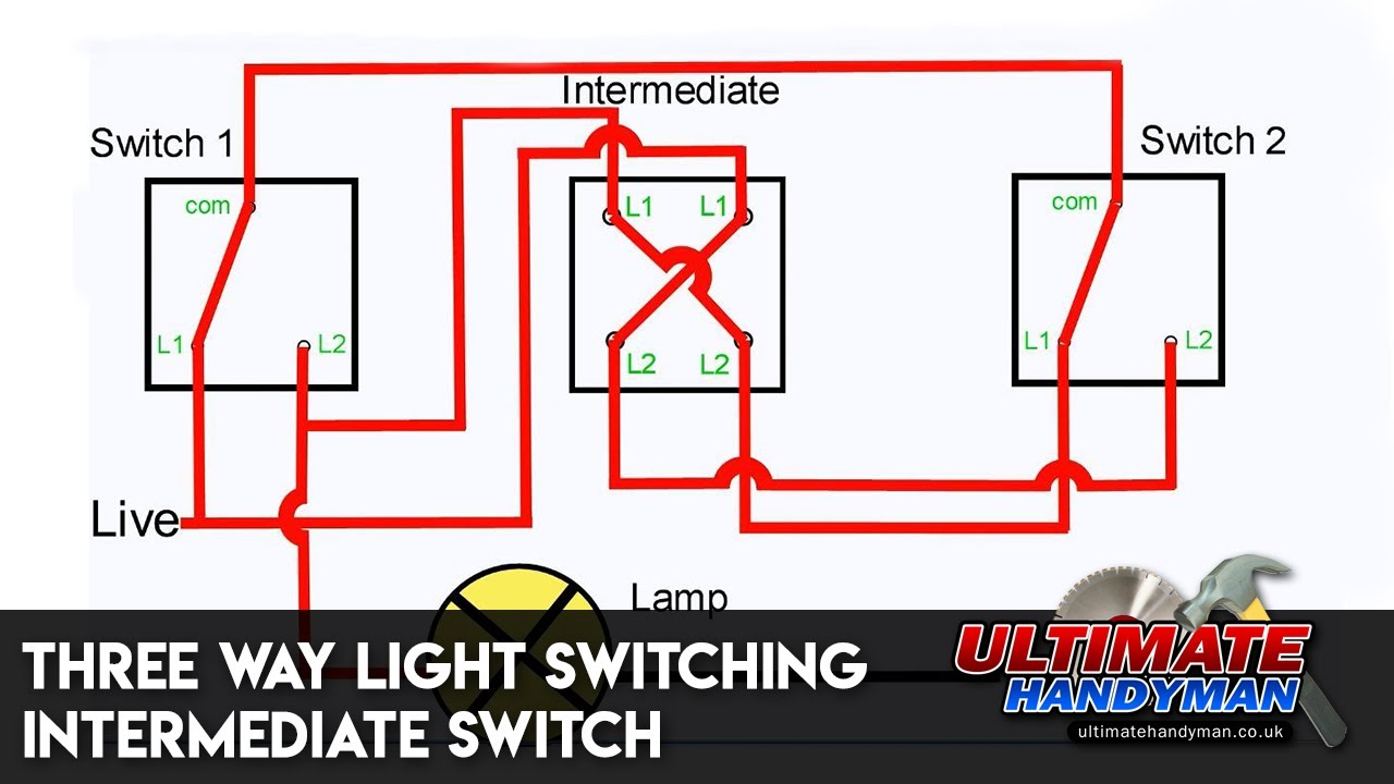
Three way light switching Intermediate switch YouTube
By Paul Evans - Jun 4, 2019 8 Intermediate switch lighting circuits. In this video we're going to be looking 4 different ways to control a light using 3 separate switches and then also two ways to control a light using 4, or more switches.
2 3 way switch wiring diagram
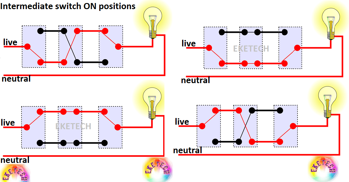
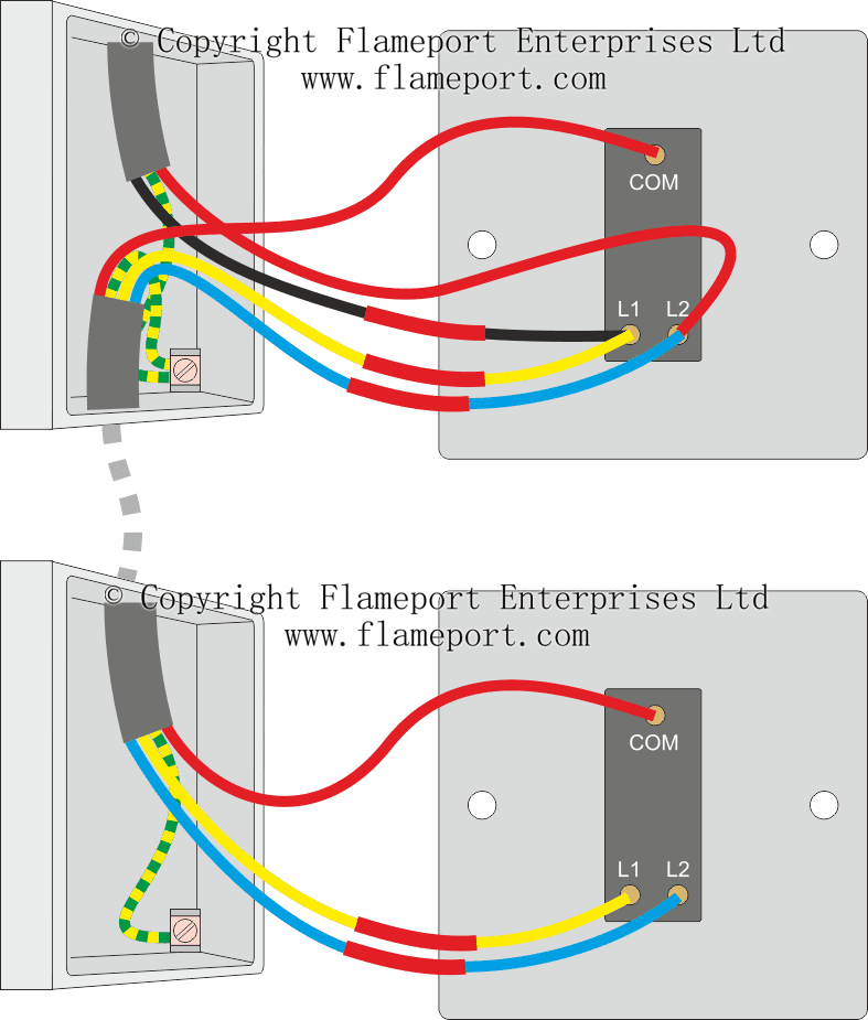
In an intermediate switch, there are four terminals by which it changes the flowing of electric current from one circuit to another (see fig 1 & 2) and is also known as Four-Way Switch (Three Way Switch in the UK & EU). It has the ability to ON and OFF the electric supply by two ways or control the single circuit from more than two places.

Intermediate Switch Wiring Diagram Nz
0:00 / 15:16 Intermediate switch wiring |Different types explained| 3-Way Switch/Intermediate Switch Connection. Obloni channel1 2.04K subscribers Subscribe Subscribed 3.5K views 3.

Wire Switch, Line Diagram, Electrical Wiring Diagram, Electrical Connection, Electric Motor
One Way Switch This type of switch is mainly used when you have only a single switch for a single light. The best example of this switch is a ceiling light in the bedroom. These switches are not expensive so used in simple circuits. One Way Type Two Way Switch
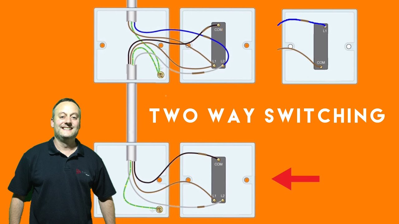
two way light switch diagram
A typical intermediate switch wiring diagram consists of two switches wired together. Both the switches must be operated simultaneously in order to turn the lights off or on. As the name suggests, the intermediate switch lies between two or more switches, creating a "flow" of energy that can be controlled from each of the switches..
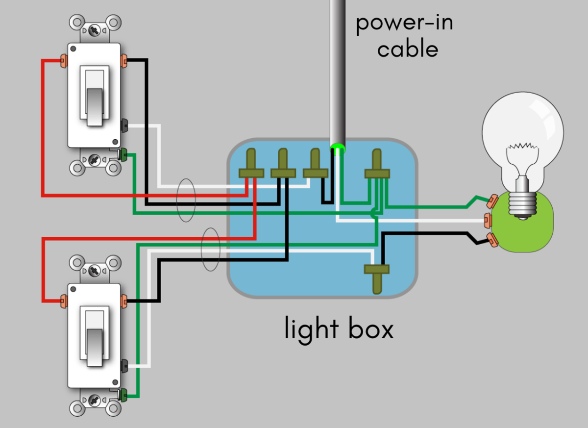
How to Wire a 3Way Switch Wiring Diagram Dengarden
A two-way intermediate switch wiring diagram is a graphical representation of a circuit. It shows the components of the circuit as simplified shapes, and the power and signal connections between the devices. This diagram provides information on how to install the two-way intermediate switch in a circuit.
Intermediate switch connection and wiring diagram
A schematic diagram is a representation of the electrical circuit, showing all the components and how they are connected. Schematic diagrams are useful in determining the exact location of wires and components, as well as identifying the circuit's power sources.

1 Gang Intermediate Switch Wiring Diagram Organicfer
In short, a 4-Way Switch (US) or 3-Way (Intermediate) Switch is a DPDT is a "Double Pole Double Throw" switch having four terminals. 4 - Way Switch - DPDT, Double Pole, Double Throw - US - NEC 3 - Way Switch - DPDT, Double Pole, Double Throw - UK - IEC Difference Between 4-Way and Double Pole Switches (US - NEC).
20 Best Intermediate Light Switch Circuit Diagram
Legrand intermediate switches are used to control one or more electrical loads from another location, usually from a wall. They are commonly used to control lighting fixtures, ceiling fans, or other devices in the home. In order for the switch to work properly, it must be wired correctly.
light switch loop wiring diagram
https://ryb.com.bd/ Intermediate switchAn intermediate switch is a three way light switch. It is used when you have three or more switches controlling one li.
Intermediate switch connection and wiring diagram
Procedure: Prepare the wiring diagram according to the layout diagram and draw on the board with the right measurements. Set 1 ½ and 1 ¼ clips according to the number of wires. Then, set 1/1.3 red wire and 1/1.3 blue wire on the board. Then, set the PVC sunk box and round box.
3 way intermediate switch wiring diagram pdf DHNX Wiring Diagram
A wiring diagram is a graphical representation of the electrical circuit that shows how the different components are wired together. The diagram will usually include wire colors, as well as labels for each of the components. Intermediate light switches are among the most common devices found in homes, which is why it is important to understand.